 The two most common types of bipolar stimulating electrode are the twisted pair bipolar electrode and the concentric bipolar electrode shown on the right.
Neurophysiology is used to study the electrical activity of the brain. It invoves the placement of at least one recording electrode in the brain. Recording can be intracellular or extracellular. Juxtacellular recording is a special case of exracellular recording where the activity of a single neuron is recorded by having the recording electrode juxtaposed (placed along side) the neuron. Extracellular recording can be done either in the acute or chronic preparation. Intracellular recording is limited to the acute preparation. Recording can also be done either in vivo or in vitro. The slice preparation is an example of the latter. In general, the smaller the population of cells that you wish to record from, the smaller the electrode tip and the higher the electrode impedence must be. Single units require a pipette with a tip diameter of 1 or 2 µ and an impedence of several M Ohms. Field potentials can be recorded with a tip diameter of 10 to 50µ and a an impedence of less than 1 MOhm. EEG can be recorded with a nail.
Recording of spontaneous acivity can be done in a preparation where a single electrode is lowered into the brain to record the ongoing electrical activity. Recording is done using either a micropipette or a metal recording electrode. Micropipettes must be filled with a conducting solution such as 2 M sodium chloride or sodium acetate. A metal recording electrode may consist of a single insulated wire or an assembly of several wires such as in the case of stereotrodes or tetrodes. Carbon fibre electrodes have recently become popular for unit recording. They are similar to micropipettes, but have a single carbon fibre projecting from the tip of the pipette.
In addition to recording spontaneous activity, the activity evoked by sensory, electrical, or chemical stimuli can also be recorded. Electrical stimulation is accomplished using a stimulating electrode. Stimulating electrodes can be bipolar or monopolar. In the case of monopolar electrodes the current delivered can be either anodal, or cathodal. With bipolar electrodes one tip is the anode and the other is the cathode (cathode emits electrons, anode collects electrons). Chemical stimulation maybe administered by a micropipette either iontophoretically or by pressure ejection using a picospritzer. Chemicals can also be delivered via cannula or retrodialysis. A "Drool" pipette consisting of a recording pipette with a large tip (40-50µ) containing the chemical to be administered can sometimes be used as both stimulating and recording electrode. The chemical leaks from the pipette onto the target cells whose activity is recorded by the same pipette. It is sometimes possible to deliver chemicals systemically via IP or IV injection. In the case of in vitro experiments, a chemical is applied by washing it over the tissue in a bath.
Electrode Summary
Micropipettes are manufactured from capillary glass tubing. There are many types of capillary glass of varying construction,length, and thickness. The most important features from a practical viewpoint are wall thickness and the presence or absence of a filling fibre. Thin walled pipettes are ideal for making pipettes with short fine tips. The down side is that the thin walled tubing is easily crushed by some pipette pullers. A filling fibre is a small glass fibre fixed to the inner wall of the capillary tubing. This fibre greatly facillitates the filling of the fine end of the pipette tip. Capillary glass with filling fibres should probably be used whenever the pipette tip will be <5µ in diameter.
Once the capillary glass has been chosen, it must be traansformed into a pipette, using a pipette puller. The capillary tubing is threaded through the heating element and clamped in place. The pipette puller has dials to control the heat and the solenoid. The solenoid governs how much force will be applied to the pull. By playing around with these controls you should be able to come up with settings which will provide you with an appropriate tip (short and stubby, long and slender,...)
Generally a pulled pipette will have a tip diameter of <2µ. You can determine the tip diameter using a microscope. If the tip is not of the appropriate diameter it can be broken back with a very fine pair of forceps, or by brushing or tapping the tip on a tissue.
The next step is to fill the pipette. For very fine tipped pipettes constucted from capillary tubing with a filling fibre, the tip of the pipette can be back-filled. Dip the uncut end of the pipette in the filling solution and the solution will be carried to the tip by capillary action. Only the tip will be filled in this manner. The remainder of the pipette is filled with a long slender needle, silica fiber or pipette filler. A handy pipette filler can be constructed by heating a 1cc plastic syringe barrel until it is very soft and pulling it so that the barrel is pulled into a long slender thread which can be inserted into the pipette barrel. It is imprtant when filling the pipette that all air bubbles are removed. An uncoated silver wire with a connector pin is then lowered into the filling solution as illustrated above and the micropipette is ready to use. If the micropipette is being used solely for ejecting, the silver wire is unnecessary.
Micropipette tips are extremey fragile, so insure that the elecrode hole is free of debris and that the dura mater is removed.
Once the micropipette is lowered into the brain, the silver wire must be connected to the G1 pole of the amplifier input. The G2 pole is connected to ground. For simplicity, usually a hole is drilled into the rat's skull and a screw is threaded into the hole. This screw serves as a ground point for recording electrodes and monopolar stimulating electrodes. The signal on the screw will be subtracted from the signal on the pipette, thereby eliminating background noise. The amplifier, as the name suggests, amplifies the signal. It also allows you to filter the signal using high pass and low pass filters. If you are looking at units, your signal will be in the microvolt range and you will probably want to amplify 5,000 to 20,000 times. For field potentials, your signal will be in the millivolt range and you will probably want to amplify 50 t0 200 times. For Field potentials, the high pass filter should be set to 3 Hz and the Low pass set to 3KHz. The 60Hz notch filter is left in the "out" position. For units, the high pass filter is set at 600Hz and the Low Pass filter at 3 KHz. For unit recording, the 60Hz notch filter should be in the "in" position.
The output of the amplifier is sent to the oscilloscope.
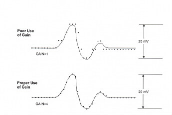
The operation of the oscilloscope is beyond the scope (pun intended) of this introduction. In simple terms the oscilloscope provides you with an analog display (unless you are using a digitial osccilloscope)of the signal from your rat. The oscilloscope display is much like a graph with volts plotted on the vertical axis and time on the horizontal axis The oscilloscope screen is marked off with a grid of boxes. The dials for the vertical gain (voltage) and the horizontal gain (time base) tell you how maany volts or seconds are displayed per box.
Exercise: If the vertical gain is set to 200mV and the event you're recordin is 3 boxes high, how big is the signal from the rat if the amplifier gain is set to 10,000.
Answer: 3 boxes is 600 mV. 600mV divided by 10,000 is 60µV. The signal from the rat is 60µV.
The oscilloscope does not process the signal in any way. The signal is displayed and sent on its way unchanged. The output of the oscilloscope can be recorded to FM tape, sent to a chart recorder to produce a hard copy of the output and/or sent to an A/D Converterto be converted to a digital signal suitable for computer storage and analysis. Almost all data is now stored on and analyzed by computer, so the signal's next stop is the A/D Converter.
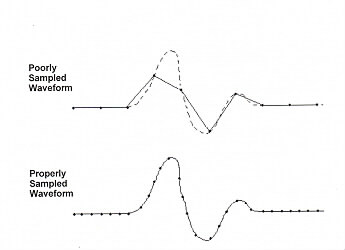
The A/D Converter converts the analog signal (Volts/msec) to a digital signal. Using computer software the A/D Converter is given instructions to sample the incoming signal at a specified rate read the voltage and convert the voltage to a number. For exampe the A/D Converter might be instructed to collect 600 points at 20 KHz. A digitization rate of 20,000KHz is 20 points per msec or 1 point every 50 µsec. With these instructions the A/D Converter would collect and digitize 30msec of the incoming signal. It is critical that the digitizing rate be set appropriately. If the rate is too slow, there will not be enough points to properly characterize the waveform. If the digitization rate is set too high, the wave form will be properly characterized, but computer memory will be wasted. Collecting 150,000 points per second can use up a lot of memory in a short time.
In addition to setting the digitization rate of the A/D Converter, the digitization range must also be set. There are 4 possible range settings :
The A/D converter will assign each voltage a whole number between 0 and 4095. Because ther are only 4096 numbers to work with, the resolution will be different for each setting.
As a general rule, you always want to set the resolution as high a possible, but you mustn't choose an A/D range that is smaller than the incoming signal or the signal will be "clipped".
Many electrophysiological experiments examine the activity evoked by electrical stimulation. There are many types of stimulators and many forms of electrical stimulation.
In some stimulators, the intensity of stimulation is varied by controlling the current in others the voltage is manipulated. In the literature, the stimulation current is usually reported, so it makes life easier to use a constant current stimulator.
Beyond the choice between voltage or current stimulators, there are many other decisions to be made: monopolar vs. bipolar stimulation, monophasic vs biphasic, anodal vs. cathodal and trains vs pulses.
Bipolar stimulation is delivered through a bipolar electrode. As the name suggests a bipolar electrode has 2 poles.The two most common types of bipolar stimulating electrode are the twisted pair bipolar electrode and the concentric bipolar electrode shown on the right.
Monopolar stimulation is delivered through a monopolar electrode. A monopolar electrode consists of a single insulated wire whose exposed tip is located in the target. The current is delivered through the wire, stimulating the tissue. The circuit is usually completed by the current travelling to a screw threaded into the skull of the rat. The screw is in turn connected by a wire to the other terminal of the stimulator.
The diagrams below show typical square wave stimulating pulses. The monophasic example shows a single positive going pulse. A single negative going pulse can be administered by changing the polarity. There is usually a switch on the stimulator which allows you to do this. If there is not a polarity switch, yoou can change polarity by reversing the manner in which the electrode leads are connected to the stimulator ( or in the case of monopolar stimulation, reverse the electrode and ground connections.) The biphasic example shows a positive going pulse immediately followed by a negative going pulse. Not all stimulators are equiped to deliver biphasic stimulation. The last diagram shows a train of positive going square wave pulses. Below the diagram of the stimulation train, a series of segments illustrate the component parts of the train.
On the right is a diagram illustrating the basic circuit of the recording setup. The computer runs the software that controls the experiment.
Although the amplifier does filter the signal to some extent, the recording setup acts as a large antenna for ambient electrical noise. Unchecked, the signal from the rat can become lost in this electrical interference. It is critical that the entire setup be properly grounded. Each element of the setup including the rat and the stereotaxic frame must be connected to a common grounding point. Usually most of the electronic equipment is rack-mounted and the rack serves as a convenient grounding point. All of the electrical equipment being used in the setup should be plugged into a single power bar. If these precautions do not eliminate the electrical noise, turn off fluorescent lighting and unplug any devices that are not being used (radios, drills, illuminators...). If these precautions are not sufficient to eliminate, or reduce noise to accepable levels, it may be necessary to use a Faraday cage. A Faraday cage is a recording chamber constructed of copper screening. If a Faraday cage is not available, it is sometimes effective to surround a portion of the recording setup with aluminium foil and connect the foil to ground using aligator clips. Try to avoid this. It looks tacky.